Congratulations, all!
Author: N3RTW
-
VA Metro Meeting Feb 10, 2026
We had a great meeting at the Lazy Dog In. Members learned about the upcoming 5M contests and Tom NC3Y told us stories of med school.
-
Sleep Strategy for Contesters
Rick N0YY has added an article to our presentations section about Sleep Strategy for Contesters.
-
Two new antenna articles
VA Metro Chapter Chair Stephen Johnson, N2FT, has shared two articles on antenna design:
-
Designing an Amateur Radio Antenna Installation using a Tailored Commercial System Engineering Process
Designing an Amateur Radio Antenna Installation using a Tailored Commercial System Engineering Process
Stephen P. Johnson, D.Sc. N2FTWhen I moved into my current home twenty years ago in a community with a homeowner association (HOA), I knew that setting up an effective antenna system that would not arouse the ire of the architecture review board would be a challenge. I operated mobile on VHF and HF for many years and operated a low “inverted vee” in the backyard for a while, but convenience and performance were lacking. I primarily wanted to operate HF DX contests from home and make reasonable numbers of contacts.
In my job as a professional system engineer and systems architect with the Raytheon Company (now retired), I was periodically called upon to help envision and design complex systems to meet challenging customer requirements. My company has developed and comprehensively applies a thorough systems engineering process defined by an Integrated Product Development System – a collection of business processes and tools that Raytheon uses throughout the product lifecycle. This system is applied to the complex task of satisfying customer needs with optimized system designs.
Faced with the need for a custom antenna system for my home amateur station, I decided to leverage my professional systems engineering background and apply some of the engineering analysis and design techniques I have used at work to design an antenna system that would be reasonably low profile yet provide adequate performance. Although this antenna design may provide the basis for others to build similar antenna systems through replication or adaptation, the primary thrust of this article is to present a simplified system engineering approach and the problem solving techniques I used so the reader can understand the overall thought process and then apply similar methods to solve their own amateur radio system design problems. It should be noted that I am not a professional RF engineer, so I approach this job with the RF technical skills of a typical technically-oriented amateur operator.
Please see Stephen’s full article – Designing an Amateur Radio Antenna Installation using a Tailored Commercial System Engineering Process
-
A Tri-Band Parasitic, Portable Vertical Array
2024 ARRL Antenna Design Submission for 80-10 meter Category
A Tri-Band Parasitic, Portable Vertical Array
Stephen P. Johnson D.Sc. (N2FT)
and
Thomas H. Schiller (N6BT)
The subject of this submission is a portable tri-band parasitic vertical array designed for locations with limited space and time. The array uses a single ¼ wave multi-band driver and three single-band reflectors to provide low-angle gain on 20, 15, and 10 meters. It supports operations in N2FT’s HOA-controlled environment by providing a relatively low-profile design that can be quickly installed for the duration of a contest and then stored. This specific implementation was designed by N2FT based on the many technical innovations developed by his friend and antenna Elmer, N6BT.
Tom Schiller, N6BT, has been building parasitic vertical arrays for DX contests and DX expeditions for decades. They are described in his superb book, “Array of Light”, which is now in its fourth edition [1]. Tom’s early successful efforts for Team Vertical (co-founded by Kenny Silverman, K2KW) featured single-band, two element vertical parasitic arrays using two elevated gull-wing radials. He also paralleled two of these arrays for greater gain. Tom later developed the commercial Sigma product line utilizing a compressed vertical dipole capacity loaded on the top and bottom (imagine a large letter “I”), then a simplified, bottom-fed design, the Bravo series, which only utilized bottom capacity loading. Both of these designs were single and multi-band using either manual length changes, or relay-controlled inductors at the feed points. He continued research and eventually developed the vertical-open-ring (VOR) design used on this project: an open ring counterpoise for verticals that replaces the elevated radials with roughly equivalent performance and requires minimal space. Finally, Tom discovered that by using concentric rings for each band of interest, he could operate on multiple bands with an adjustable vertical (i.e., SteppIR).
The fan dipole has been a well-known amateur multi-band antenna design for even longer. It is unclear when the idea was first applied to multiband vertical antennas, but Callum, M0MCX, has done a great deal to popularize the multiband fan vertical using wire elements with his DX Commander offering [2]. N2FT applied these design ideas using aluminum tubing elements to achieve tri-band operation.
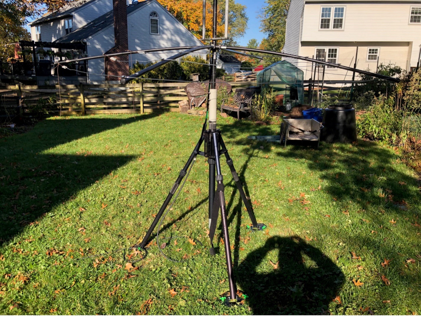
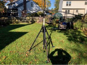
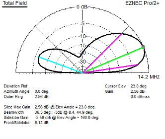
The antenna described in this submission for 20,15, and 10 meters, combines N6BT’s concentric open ring counterpoise, a variant of the fan vertical, aluminum tubing radiators, and movable supports to produce an array that is portable. It provides about 4dB of gain at low elevation angles. The “beam” can be rotated by picking up and moving a reflector using the “Arm-strong” method. It has low visibility from the street in N2FT’s backyard and is installed for contest weekends and then stored to reduce the chance of HOA intervention. N2FT has used the antenna successfully in numerous DX contests. The antenna would also be suitable for POTA (but probably not SOTA) activations. It is likely a lower weight variant could be easily designed and constructed.
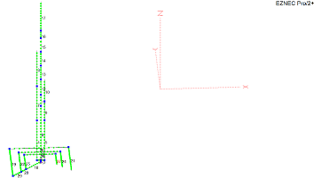
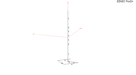
This implementation was developed using surplus aluminum antenna parts donated by generous members of N2FT’s contesting club (Potomac Valley Radio Club). N2FT modeled the design using NEC-5, EZNEC, and AutoEZ. The design can be implemented as is, but there are other potential implementations that can be implemented using materials from the individual ham’s junk-box. This would require adjusting the EZNEC model to reflect different radiator diameters or materials. NEC-5 is recommended due to its ability to model closely spaced wires. NEC-2 gives different and often less reliable results.
N2FT would like to underscore his gratitude to N6BT for his inspiration, kind mentorship, and for being the best Antenna Elmer any OM could want.
Many thanks to Dan McGuire (AC6LA) for his excellent AutoEZ EZNEC optimization tool and for priceless and incredibly responsive help with the AutoEZ optimizer set-up and array optimization. Thanks also to LLNL for developing the NEC antenna modeling tool, and to Roy Lewallen (N7EL) for developing EZNEC and his contributions to the antenna modeling community.
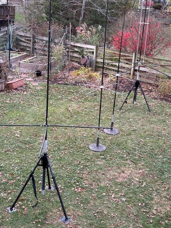
The Array
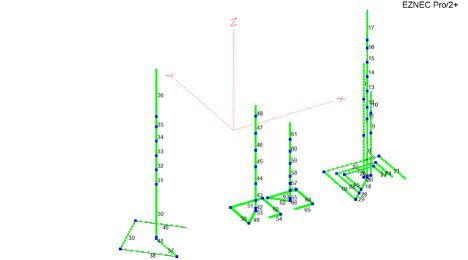
The array consists of the tri-band driver and a separate reflector for each band. Due to the proximity of the 10 meter and 15-meter counterpoises, there is some noticeable coupling between them, and the orientation of the rings shown seems to minimize the coupling. See the attached wires list for “wire” lengths and diameters.
The Driver
Driver Ring Supports and Radiator Support

The driver uses three concentric open rings for the counterpoise and three parallel radiators made from aluminum tubing. The base of the radiators is an aluminum member cut from surplus aluminum stock using a carbide-tipped blade on a table saw and drilled slightly smaller than the element diameters. Non-conductive material could be used, but then wires would be required to connect each of the vertical radiators, and the EZNEC model would require adjustment. This member supports the radiators and provides for a tight fit and electrical connectivity when the halves are bolted together. The radiators are separated and reinforced by an acrylic spacer about 4 feet up (non-critical). The 20-meter radiator is centrally placed and the 10 and 15-meter radiators are offset about 6” to either side. This order may not be optimal; an alternative would be to place the 20-meter and 10-meter radiators on the ends to minimize coupling between these harmonically related bands. Changing the order would require adjustments to the EZNEC model due to the element’s interactions.
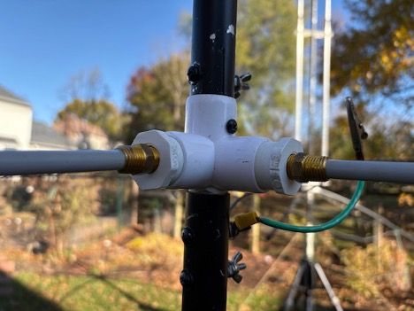
PVC 5-way connectors (1”) are drilled out to become 6-way connectors to support the rings. The ring supports in one implementation are 3/4” PVC pipe. Other mechanical arrangements have been tried to reduce the 1” diameter mounting hole to use commonly available 3/8” fiberglass rod. None of the adaptations have been fully satisfactory. An alternative would be to use a piece of solid material drilled out for the 3/8” rods and the vertical support, and the next version of the antenna will likely use this approach.
The shared first side of the driver’s three concentric rings is made from aluminum tubing to handle the relatively high current near the feed point. N6BT discovered that this provides slightly less loss than an all-wire implementation. The remainder of each ring is made from 12 AWG PVC insulated wire.
The driver and 20-meter reflector are supported by tripods that were on hand. Fiberglass tubing from reused quad spreader sections and fiberglass tubing sections purchased from Max Gain Systems was used to insulate the radiating elements and counterpoise from the tripod. The driver is fine-tuned for SWR after the reflectors are installed. The tripod is normally staked down and guyed to prevent the driver from blowing over in high winds. This occurred once before the tripods were staked down, and it resulted in damage to the PVC 6-way coupler.
The model was designed to match the currents into the radiator and counterpoise as closely as possible to maximize emission by the vertical radiator, minimize common-mode current on the feedline and the consequent balun heating. A choke balun is used on the feedline to reduce unwanted radiation by the feedline.
Example Adaptation of 1” PVC 6-way to host 3/8” fiberglass rod with Reflector Jumper
The Reflectors
The reflectors are simpler versions of the driver, consisting of one vertical radiator and one ring. The 20-meter reflector was implemented to be supported by a tripod identical to the driver. The other reflectors are supported by sections of old fiberglass quad spreaders that were in the junk-box. The 15-meter and 10-meter reflectors are held up by patio umbrella stands commonly available online. The 20-meter reflector and driver could also be implemented using this approach, but careful staking of the stands and guys would be required to survive high winds. Each radiator includes a jumper with an alligator clip that connects the radiator and counterpoise in normal operation. This jumper is easily detached to disable the reflector. This allows the array to be used in omnidirectional mode for that band, e.g., to work South America while the array is pointed towards Europe. This has proven to be a handy feature. If greater gain is needed in another direction (e.g., for working JA after Europe closes), the reflector can be picked up and moved to steer the beam for that direction.
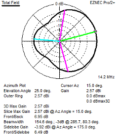
20 Meter Array Patterns from Model
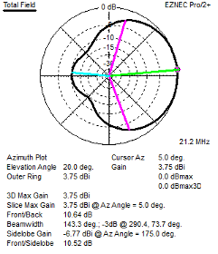
15 Meter Array Patterns from Model

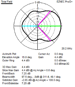
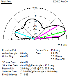
10 Meter Array Patterns from Model
SWR from Model and Measurements
20 Meter SWR into 50 Ohm Feedline

20 Meter SWR into 1:2 UNUN
Hairpin matches are frequently used for single-band antennas to match lower impedances to 50-ohm feedlines. In this case, a 1:2 UNUN was used to achieve results that would apply to all three bands of interest.
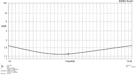
As Built SWR Measured at Antenna (at 50 ohms)
Measurements were made using a Rig Expert A-55 Zoom calibrated with the reference plane at the antenna. No 1:2 UNUN was used for as-built measurement. All the as-built SWR measurements were made before the latest model optimization, but any changes to these measurements are expected to be minimal based on previous similar design iterations.
Frequency SWR 14.0 1.9 14.1 1.6 14.2 1.4 14.3 1.4 14.35 1.4 15 Meter SWR into 50 Ohm Feedline
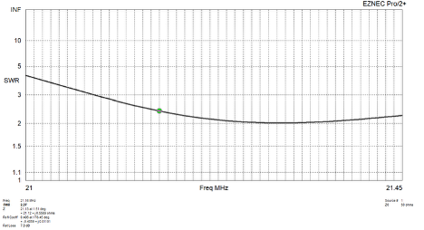
15 Meter SWR into 1:2 UNUN
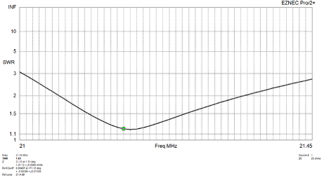
As Built SWR Measured at Antenna (measured at 50 ohms)
Frequency SWR 21.0 2.8 21.1 2.2 21.2 1.7 21.3 1.4 21.4 1.4 21.45 1.4 10 Meter SWR into 50-ohm Feedline
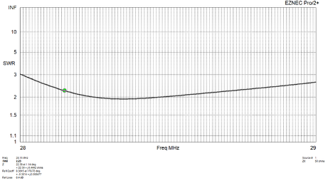
10 Meter SWR into 1:2 UNUN
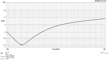
10m SWR Measured from As-Built Antenna (at 50 ohms)
As Built SWR Measured at antenna
Frequency SWR 28.0 3.0 28.2 2.7 28.4 2.1 28.6 1.8 28.8 1.6 29.0 1.7 29.2 1.9 Bill of Materials
Because this antenna was built using materials from N2FT’s junk box, it is unlikely that any subsequent version would or should be implemented the same way.
For this reason, in addition to the EZNEC wires list is given to provide the lengths and diameters of each of the radiating elements, a notional bill of materials is also provided with some design alternatives.
- Driver and Reflectors
- Driver or Reflector base (tripod, umbrella stand, stake in ground)
- Driver support (non-conducting) – insulating tubing (fiberglass, PVC), guy ropes, stakes for base
- Radiator support (member to hold three radiators) – aluminum, black Delrin, HDPE, etc)
- Radiator Spacing – nonconducting member to reinforce and support radiators
- Aluminum tubing for radiators
- Stainless Hose clamps or other means to join radiator sections
- Aluminum tubing for first segment of concentric rings
- Wire for the remainder of concentric rings.
- Insulators for ring ends
- Terminals, stainless hardware
EZNEC Pro/2+ ver. 7.0
Tribander with open ring                     12/16/2024     12:24:15 PM
--------------- WIRES ---------------
No.            End 1     Coord. (in)              End 2     Coord. (in)       Dia (in)  Segs        Insulation                Wire Loss
Conn.      X       Y       Z       Conn.      X       Y       Z                         Diel C  Thk(in)  Cond(S/m)  Perm
1         W18E1    264.9,      0,     68      W2E2    264.9,      0,     70     0.875   2           1        0    4E-08       1
2          W4E1    260.4,      0,     70      W3E1    264.9,      0,     70     0.875   3           1        0    4E-08       1
3          W6E1    264.9,      0,     70      W5E1    269.4,      0,     70     0.875   3           1        0    4E-08       1
4          W2E1    260.4,      0,     70      W7E1    260.4,      0,  122.5     0.875   14          1        0    4E-08       1
5          W3E2    269.4,      0,     70      W9E1    269.4,      0,  122.5     0.875   14          1        0    4E-08       1
6          W1E2    264.9,      0,     70     W11E1    264.9,      0,  141.5     1.125   19          1        0    4E-08       1
7          W4E2    260.4,      0,  122.5      W8E1    260.4,      0,  167.5      0.63   12          1        0    4E-08       1
8          W7E2    260.4,      0,  167.5              260.4,      0,  214.5     0.375   13          1        0    4E-08       1
9          W5E2    269.4,      0,  122.5     W10E1    269.4,      0,  147.5      0.63   7           1        0    4E-08       1
10         W9E2    269.4,      0,  147.5              269.4,      0,  176.5      0.44   8           1        0    4E-08       1
11         W6E2    264.9,      0,  141.5     W12E1    264.9,      0, 156.25       1.1   4           1        0    4E-08       1
12        W11E2    264.9,      0, 156.25     W13E1    264.9,      0,  176.5         1   6           1        0    4E-08       1
13        W12E2    264.9,      0,  176.5     W14E1    264.9,      0,  194.5     0.875   6           1        0    4E-08       1
14        W13E2    264.9,      0,  194.5     W15E1    264.9,      0,212.625      0.75   6           1        0    4E-08       1
15        W14E2    264.9,      0,212.625     W16E1    264.9,      0,230.625     0.625   4           1        0    4E-08       1
16        W15E2    264.9,      0,230.625     W17E1    264.9,      0, 240.75       0.5   4           1        0    4E-08       1
17        W16E2    264.9,      0, 240.75              264.9,      0,  279.5     0.375   12          1        0    4E-08       1
18         W1E1    264.9,      0,     68     W25E1    246.5,  -18.4,     68      0.75   8           1        0    4E-08       1
19        W29E2    230.3,  -34.6,     68     W20E1    230.3,   34.6,     68       #12   20          1        0    4E-08       1
20        W19E2    230.3,   34.6,     68     W21E1    299.5,   34.6,     68       #12   12          1        0    4E-08       1
21        W20E2    299.5,   34.6,     68              299.5,  -25.5,     68       #12   16          1        0    4E-08       1
22        W28E2    240.5,  -24.4,     68     W23E1    240.5,   24.4,     68       #12   13          1        0    4E-08       1
23        W22E2    240.5,   24.4,     68     W24E1    289.3,   24.4,     68       #12   13          1        0    4E-08       1
24        W23E2    289.3,   24.4,     68              289.3,  -14.5,     68       #12   12          1        0    4E-08       1
25        W28E1    246.5,  -18.4,     68     W26E1    246.5,   18.4,     68       #12   10          1        0    4E-08       1
26        W25E2    246.5,   18.4,     68     W27E1    283.3,   18.4,     68       #12   10          1        0    4E-08       1
27        W26E2    283.3,   18.4,     68              283.3,     -9,     68       #12   10          1        0    4E-08       1
28        W18E2    246.5,  -18.4,     68     W29E1    240.5,  -24.4,     68      0.75   3           1        0    4E-08       1
29        W22E1    240.5,  -24.4,     68     W19E1    230.3,  -34.6,     68      0.75   5           1        0    4E-08       1
30        W41E2        0,      0,     70     W31E1        0,      0,    136     1.125   34          1        0    4E-08       1
31        W30E2        0,      0,    136     W32E1        0,      0, 154.25         1   10          1        0    4E-08       1
32        W31E2        0,      0, 154.25     W33E1        0,      0, 172.25     0.875   10          1        0    4E-08       1
33        W32E2        0,      0, 172.25     W34E1        0,      0,190.375      0.75   10          1        0    4E-08       1
34        W33E2        0,      0,190.375     W35E1        0,      0,208.375     0.625   10          1        0    4E-08       1
35        W34E2        0,      0,208.375     W36E1        0,      0,    221       0.5   7           1        0    4E-08       1
36        W35E2        0,      0,    221                  0,      0,  281.6     0.375   40          1        0    4E-08       1
37        W41E1        0,      0,     68     W38E2        0,    -45,     68     0.064   10          1        0    4E-08       1
38        W39E1      -45,      0,     68     W37E2        0,    -45,     68     0.064   10          1        0    4E-08       1
39        W38E1      -45,      0,     68     W40E2        0,     45,     68     0.064   10          1        0    4E-08       1
40                    41,      4,     68     W39E2        0,     45,     68     0.064   10          1        0    4E-08       1
41        W37E1        0,      0,     68     W30E1        0,      0,     70     0.064   2           1        0    4E-08       1
42        W53E2    124.7,      0,     70     W43E1    124.7,      0,     80     1.125   10          1        0    4E-08       1
43        W42E2    124.7,      0,     80     W44E1    124.7,      0,    101         1   10          1        0    4E-08       1
44        W43E2    124.7,      0,    101     W45E1    124.7,      0,    122     0.875   10          1        0    4E-08       1
45        W44E2    124.7,      0,    122     W46E1    124.7,      0,    143      0.75   10          1        0    4E-08       1
46        W45E2    124.7,      0,    143     W47E1    124.7,      0,    164     0.625   10          1        0    4E-08       1
47        W46E2    124.7,      0,    164     W48E1    124.7,      0,  185.5       0.5   10          1        0    4E-08       1
48        W47E2    124.7,      0,  185.5              124.7,      0,  199.7     0.375   10          1        0    4E-08       1
49        W53E1    124.7,      0,     67     W50E1    104.7,    -20,     67       #12   24          1        0    4E-08       1
50        W49E2    104.7,    -20,     67     W51E1    104.7,     20,     67       #12   30          1        0    4E-08       1
51        W50E2    104.7,     20,     67     W52E1    144.7,     20,     67       #12   30          1        0    4E-08       1
52        W51E2    144.7,     20,     67     W54E1    144.7,    -20,     67       #12   20          1        0    4E-08       1
53        W49E1    124.7,      0,     67     W42E1    124.7,      0,     70       #12   2           1        0    4E-08       1
54        W52E2    144.7,    -20,     67              130.2,    -20,     67       #12   30          1        0    4E-08       1
55        W66E2      168,      0,     70     W56E1      168,      0,     80     1.125   10          1        0    4E-08       1
56        W55E2      168,      0,     80     W57E1      168,      0,     89         1   10          1        0    4E-08       1
57        W56E2      168,      0,     89     W58E1      168,      0,     98     0.875   10          1        0    4E-08       1
58        W57E2      168,      0,     98     W59E1      168,      0,    114      0.75   10          1        0    4E-08       1
59        W58E2      168,      0,    114     W60E1      168,      0,    129     0.625   10          1        0    4E-08       1
60        W59E2      168,      0,    129     W61E1      168,      0,    144       0.5   20          1        0    4E-08       1
61        W60E2      168,      0,    144                168,      0,  165.2     0.375   20          1        0    4E-08       1
62        W66E1      168,      0,     67     W63E1      150,     18,     67       #12   10          1        0    4E-08       1
63        W62E2      150,     18,     67     W64E1      186,     18,     67       #12   20          1        0    4E-08       1
64        W63E2      186,     18,     67     W65E1      186,    -18,     67       #12   20          1        0    4E-08       1
65        W64E2      186,    -18,     67              162.6,    -18,     67       #12   20          1        0    4E-08       1
66        W62E1      168,      0,     67     W55E1      168,      0,     70       #12   10          1        0    4E-08       1
References
- Thomas H. Schiller (N6BT), Array of Light, Fourth Edition. Published by the author; Founder, Force 12, Inc.; Next Generation Antennas; Antenna Airborne Research, Inc.
- Callum, M0MCX, dxcommander.com
-
This is the new PVRC website, please use the Contact Us page to let us know of any problems!
-
News
Chapter Meetings – Chapters have been hosting meetings in person and on line. In a lot of cases members from other chapters have had opportunities to participate in meetings that they would normally not be able to attend. This will continue for the some chapters while others are starting to meet in person again. If you do not know when your chapter is meeting then go to the Chapter Listing page and contact the local Chapter Chairman for details on the next meeting. Click here for the PVRC Calendar.
PVRC Dues – PVRC has chosen not to implement an annual Dues requirement. We depend on the generosity of all our club members to finance our annual budget. In addition, active PVRC members are expected to participate and submit logs for at least two PVRC Club Competition contests per year. When contemplating your donation to PVRC, each member should consider the benefit you are receiving from PVRC and its many opportunities for your personal growth in our wonderful hobby, then donate accordingly. Direct donations to PVRC via Credit Card or PayPal may be made by clicking the “Donate” button above or below. Donations to PVRC are not tax deductible.
PVRC Scholarship Fund – PVRC established a Scholarship for distribution through the ARRL Foundation Scholarship. The Foundation Opens in October of each year. There are three ways to make a Tax Deductable Donation. 1 – Download the form from ARRL, Print it and submit it with your check. 2- Call the ARRL Fund Director, Regina Galuppi, and give her your credit card number (860-594-0291). 3- Send a donation to the PVRC Treasurer via Paypal, noting your donation is for the PVRC Scholarship Fund.
-
test post
New Post
query($query_rsChapters) or die($mysqli->error); $row_rsChapters = $rsChapters->fetch_assoc(); $totalRows_rsChapters = $rsChapters->num_rows; ?>